

Diese Maße bearbeiten wir auf Ihre individuelle Anfrage hin.
F3S
The guide tape profile F3S is designed for use in hydraulic cylinders. Mating surfaces may be both steel and chromed surfaces.
ADVANTAGES ARE
- profile geometry which is suited for use in hydraulics
- delivered yard goods may be cut simple according to the length required
- high compressive strength due to an special additive of bronze components, low friction coefficient and wear
- no stick-slip in the case of low slide speeds and high radial forces
- simple fitting groove
- available in many widths of section
- no contact of the matallic components in spite of the simple construction design
| SURFACES | |
| Guide tape F3S: | Guide tape FWS: |
| Smooth tread (standard) | structured tread (on request) |
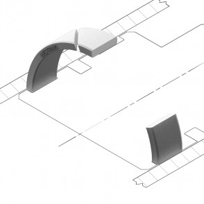
TYPES OF CUT
If the system pressure shall carry on to the seals unfettered, type a should be favored. Type S is possible, too. In any case, a well defined „open“ gap should be given. Type Z is a closed design, which in certain applications may be used as a seal. To reach an optimal service life, the gap size „e“ should be redeemed. Above all, please abide by the gap sizes of the used seal, in consideration of the working parameters given.
| APPLICATION RANGE | |
| working temperature: | - 100 °C bis + 200 °C |
| surface speed: | ≤ 5 m/s |
For special cases of application (high temperatures, speed, specific pressure, use in water, HFA-, HFB-fluids etc.) please get in contact with our consultancy service.
| MATERIAL | |
| Standard compound is: | PT052 (PTFE with 40% bronze) |
| On request: | PT062 (PTFE with 60% bronze) |
Not usable for aluminium or non-ferrous heavy metall cylinders. For this
single case please use our profile F2S in PT033 (PTFE with 25 % carbon).
| ORDER EXAMPLE PISTON GUIDE | |
| Mating surface: | Steel |
| Guide tape with smooth surface | |
| Piston diameter: | 60 mm |
| Groove: | 9,7 x 2,5 mm |
| a) meter goods: | F3S 0000 PT052 25097 A |
| b) cut by length: | F3P 0600 PT052 25097 A |
It corresponds also to a rod guidance with the same cross-section and smooth surface with a rod diameter of 55mm. Outside diameter of the groove (AD = ID + 2S)
FURTHER ORDER EXAMPLE ROD GUIDE
Guide tape with structured surface
| Rod diameter: | 45 mm |
| Outside diameter of the groove: | AD = ID + 2S) |
| Groove: | 6,3 x 2,5 mm |
| a) meter goods: | FWS 0000 PT052 25063 A |
| b) cut by length: | FWR 0450 PT052 25063 A |
It corresponds also to a piston guidance with the same cross-section and structured surface with a cylinder diameter of 50 mm. Inside diameter of the groove (ID = AD - 2S)
DETERMINATION OF THE GUIDE TAPE’S WIDTH L1
In the first instance choose the appropriate curve in the diagram for the requested guide accuracy. This one arises from the permanent deformation ε. The lower the value ε, the more precise is the guidance. The following formula provides the minimum guide tape width:
L ≥ F
Q (d - k · √2)
| d = | inner diameter [mm] |
| k = | gap [mm] |
| L1 = | guide tape width [mm] (for simplifying =groove wide L) |
| Qperm. = | zulässige spezifische Belastung [N/mm2] |
| F = | shear force [N] |
We recommend that the largest possible guidance length always be used, even if the calculation yields a smaller value. Permissible specific load Qperm. Depending on the temperature t and the respective permanent deformation ε for the compound PT052 resp. PT062.
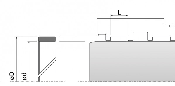
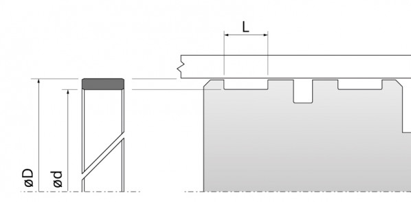
HOUSING DIMENSIONS
| Series No | Recommended | Guiding tape | Groove | |||
| d/D (mm) | S (mm) | L (mm) | d (mm) | D (mm) | max. e (mm) | |
| 15063 | ≤ 50 | 1,5 | 6,3+0,1 | D-3,0 | d+3,0 | 0,25 |
| 15100 | ≤ 50 | 1,5 | 10,0+0,1 | D-3,0 | d+3,0 | 0,25 |
| 16025 | ≤ 50 | 1,55 | 2,5+0,1 | D-3,1 | D+3,1 | 0,25 |
| 16040 | ≤ 50 | 1,55 | 4,0+0,1 | D-3,1 | D+3,1 | 0,25 |
| 17025 | ≤ 50 | 1,6 | 2,5+0,1 | D-3,2 | D+3,2 | 0,25 |
| 17040 | ≤ 50 | 1,6 | 4,0+0,1 | D-3,2 | D+3,2 | 0,25 |
| 25042 | ≥ 50 | 2,5 | 4,2+0,1 | D-5,0 | D+5,0 | 0,4 |
| 25056 | ≥ 50 | 2,5 | 5,6+0,1 | D-5,0 | D+5,0 | 0,4 |
| 25063 | ≥ 50 | 2,5 | 6,3+0,1 | D-5,0 | D+5,0 | 0,4 |
| 25081 | ≥ 50 | 2,5 | 8,1+0,1 | D-5,0 | D+5,0 | 0,4 |
| 25097 | ≥ 50 | 2,5 | 9,7+0,1 | D-5,0 | D+5,0 | 0,4 |
| 25127 | ≥ 50 | 2,5 | 12,7+0,2 | D-5,0 | D+5,0 | 0,4 |
| 25150 | ≥ 50 | 2,5 | 15,0+0,2 | D-5,0 | D+5,0 | 0,4 |
| 25160 | ≥ 50 | 2,5 | 16,0+0,2 | D-5,0 | D+5,0 | 0,4 |
| 25200 | ≥ 50 | 2,5 | 20,0+0,2 | D-5,0 | D+5,0 | 0,4 |
| 25250 | ≥ 50 | 2,5 | 25,0+0,2 | D-5,0 | D+5,0 | 0,4 |
DIAGRAMM | - PT052 + PT033 DIAGRAMM || - PT062


Permissible specific load Qperm. in relation to temperature t and the respective
permanent set for the compounds PT052 and PT062.
CALCULATION OF THE STRETCHED LENGTH “U”

CUTS

More information on our PDF
Download | Detailed product information (PDF 557.2 kB)


