Service & Dichtungstechnik
– dicht an dicht
Individuelle Dichtungssätze für Spezialanwendungen

Wir bei WESTRING sind Ihr Garant für passende, funktionale und hochwertige Dichtungstechnik. Mit mehr als 40 Jahren Erfahrung und Produkt-Knowhow bieten wir Kompetenz von der Kronenabdichtung einer Armbanduhr bis hin zur Rührwerksabdichtung der chemischen Industrie. Umfassende Beratung, schnelle Lieferung und internationaler Service sind für uns selbstverständlich. Unser gründlicher Kundendienst ermöglicht Ihnen die Werterhaltung Ihrer bestehenden Anlagen und Produktionsstrecken.
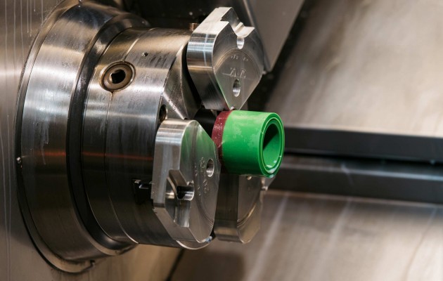
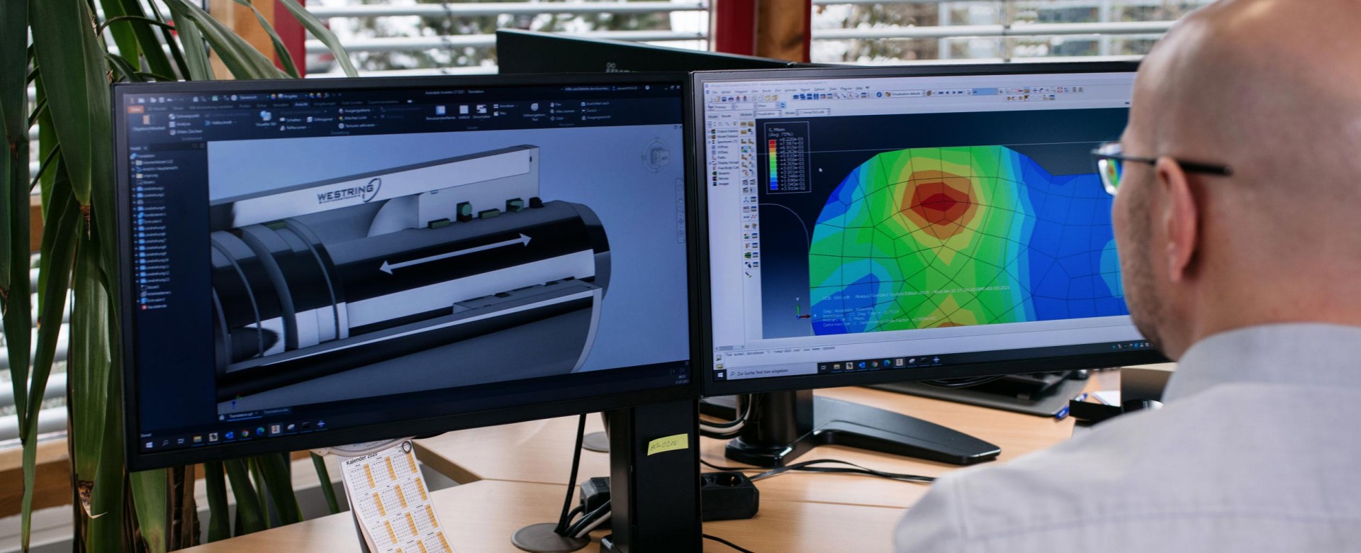
Sie suchen Prototypen-Herstellung, Kleinserien-Produktion oder die intensive Betreuung bei der Umsetzung von Großprojekten? Als ganzheitlicher Lösungsanbieter beziehen wir Sie von Anfang an in die Produktplanung mit ein und erarbeiten mit Ihnen zusammen die optimalen technischen und wirtschaftlichen Bedingungen. Unsere Ingenieure und Techniker begleiten Sie von der Zeichnungserstellung bis zum Einbau der Dichtung bei Ihnen vor Ort.
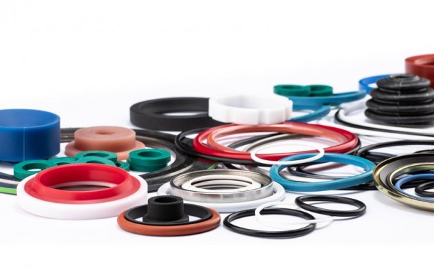
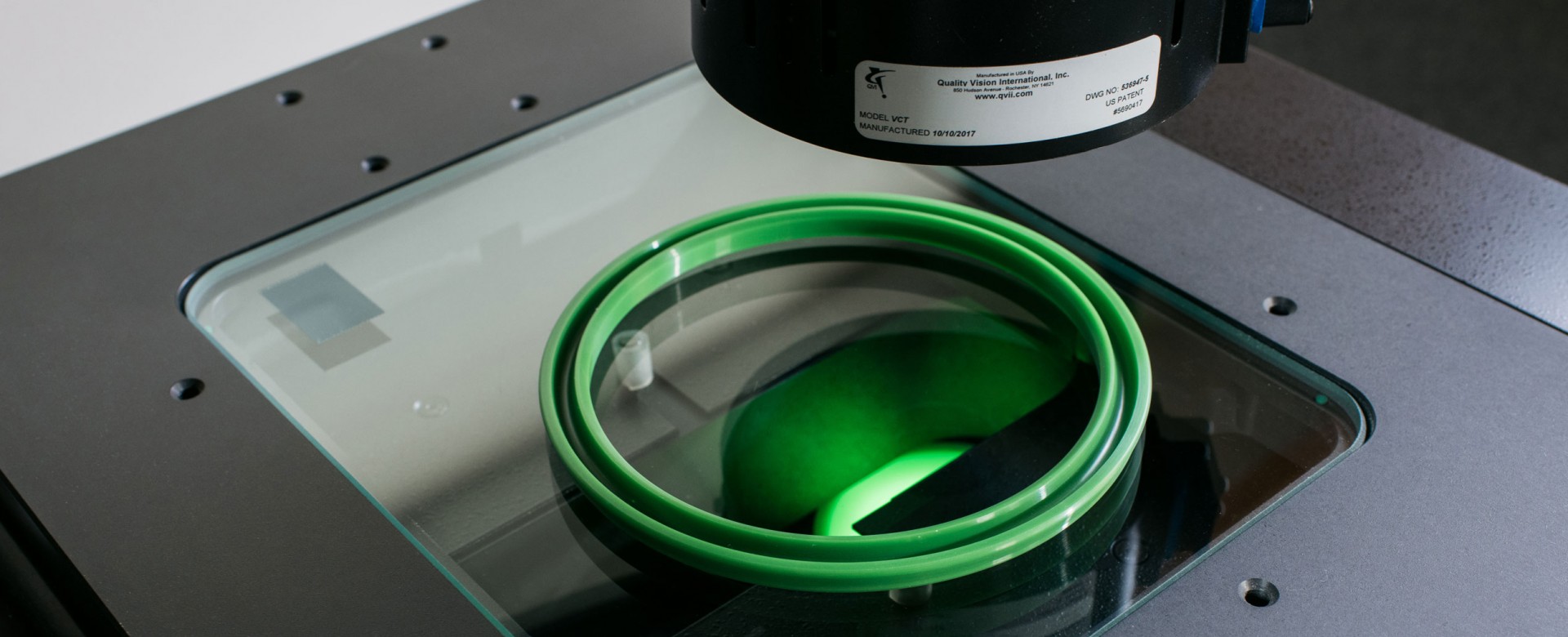
Mit unserem Sortiment bieten wir Ihnen hochwertige O-Ringe, Stangendichtungen, Kolbendichtungen, Rotordichtungen, Führungselemente, Stützringe, V-Ringe, Wellendichtungen und Flachdichtungen in verschiedenen Größen. Mit unserer Leidenschaft für diese kleinen, aber wichtigen Produkte, sind wir seit mehr als 4 Jahrzehnten ein professioneller Partner verschiedener Industriezweige weltweit.
Eine genormte Dichtung bekommt man heute auch im Buchwaren-Onlinehandel. Doch wird diese ihrer Aufgabe auch gerecht?
Dichtungen gewährleisten in Anwendung die Funktionalität pneumatischer und hydraulischer Systeme und leisten so einen wichtigen Beitrag zu umfassenden und komplexen Prozessabläufen, wie z. B. Produktionsstrecken, Hub-, Hebe- und Mischwerk, verschiedene Motoren, u.v.m.
Dichtungslösungen von WESTRING Dichtungstechnik werden den gestellten Anforderungen zu 100 Prozent gerecht.
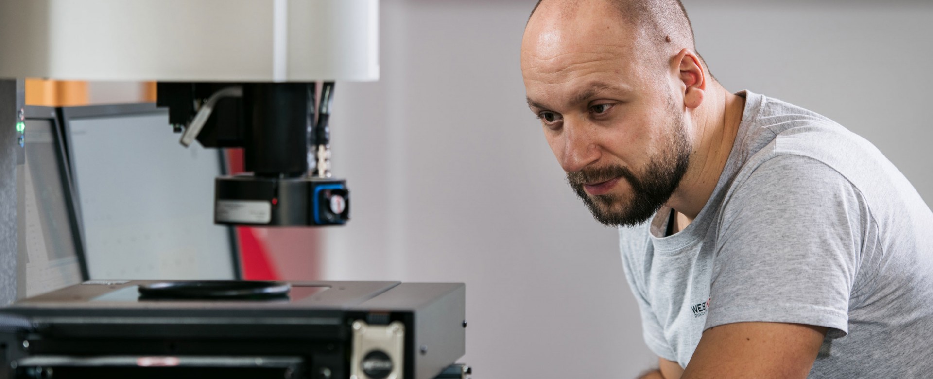
Damit wir Ihnen die optimale Dichtung liefern können, müssen wir die Parameter Ihrer spezifischen Anforderung verstehen. So fragen wir gern auch zweimal nach. Unsere Motivation liegt in Ihrer Prozessfähigkeit und Prozessstabilität und Ihrem damit verbundenen Erfolg. Unsere Geschäftstätigkeit als Händler und Produzent von Dichtungen hoher Qualität dient Ihrer Effektivität. Wir sind bei all unseren Kunden hochmotiviert die richtige Lösung und das perfekt passende Produkt zu liefern. Unsere Anstrengungen im Miteinander sind elementar, denn der Effekt ist leicht messbar: dicht ist dicht.