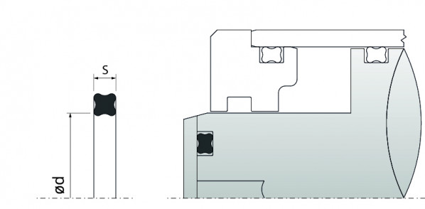
The WXS-Ring also known as Quad-Ring® or X-Ring is a four-lip-seal with a special cross section. The sizes are labelled with the inner diameter d1 and the cross section d2. The application and handling of the WXS-Ring is comparable with those of O-Rings. In many cases where the use of an O-Ring entails some disadvantages, the WXS-Ring can achieve a significant improvement of the sealing. The seal type can be used with back-up rings when high pressure and large tolerances or clearances appear. Normally back-up rings type STC (spiral shaped) are suitable. The WXS-Ring is available with the same sizes as O-Rings according to American standard AS 568 A or British standard BS 1806. A table of the available standard sizes is attached.
ADVANTAGES ARE
- security against twist
- low friction (generation of a lubricant film between the sealing lips)
- longer durability compared with an O-Ring
- marginal preload of about 5 % with regard to the cross section sufficient in most cases
- good leakage behavior due to the use of 2 sealing lips
- availability of a variety of materials
- no disturbing flash rubber (mould parting line between sealing lips)
APPLICATION RANGE
| operating pressure: | dynamic & translational: |
| ≤ 5 MPa without back-up ring | |
| ≤ 30 MPa with one back-up ring or two back-up rings | |
| dynamic & rotating: | ≤ 15 MPa with one back-up ring or two back-up rings |
| static: | ≤ 10 MPa without back-up ring |
| ≤ 40 MPa with one back-up ring or two back-up rings (Attention: Consider the permitted gap sizes in each case) | |
operating temperature: | approx. -50° up to +220°C depending on the choice of material |
| sliding speed: | ≤ 0,5 m/s (translational) |
| ≤ 2,0 m/s (rotating; only temporary) | |
| media: | NBR is very resistant against oils on mineral basis as well as flame retardant hydraulic fluids FKM is further resistant against ozone, oxygen, synthetic hydraulic fluids, petrol, solvents and chemicals EPDM is resistant against hot water as well as hot water steam and break fluids Silicone has an excellent resistance to cold; this material is often used when the material gets in contact with food The indicated information represents the maximum limit of load and is interlinked with each other. Thus for instance can lead to a reduction of applicability values when exploiting at least one maximum limit in combination with pulsating pressures. |
For special cases of application (high temperatures, speed, specific pressure, use in water, HFA-, HFB-fluids etc.) please get in contact with our consultancy service.
MATERIAL
The application area of the WXS-Ring is very large because a lot of synthetic rubbers e.g. nitrile-butadiene rubber (NBR), ethylene propylene diene rubber (EPDM), silicone rubber (MVQ, VMQ) or fluor carbon rubber (FKM) are available. As a consequence it is possible to seal almost every medium. In selecting the material which gets in contact with a special medium, you can refer to our media resistance table (drop-down menu INFO). Materials for extreme operating conditions such as FFKM, HNBR, FVMQ etc. are possible on request. A coating with e.g. PTFE can be useful to improve the sliding properties of the WXS-ring. This may be useful when assembling the WXS-ring.
MOUNTING INSTRUCTIONS
Sharp edges and bores, which have to be run over when assembling, have to be avoided during the period of constructing. Therefore the constructor is advised to include so called lead-in chamfers and curves. The angle for bores/liners and rods/shafts should be between 15° and 20° as can be seen in in pictures 1 and 2. The minimum length Y is mentioned in the relevant table 1. As far as possible the WXS-ring should also not be run over the rod for a long way with direct contact to it. It is recommended to lift the WXS-ring a little when bringing it into position.
In general the installation space should be designed according to the guidelines for groove dimensions ot the standard list and stock list. You may find these guidelines by clicking ‘INFO‘ and ‘O-RING GUIDE’ in the drop down menu. In case of certain operating conditions small variation can be necessary.
Bild 1: | Bild 2: |
Lead-in chamfer for bores and liners | Lead-in chamfer for rods and shafts |
 |  |
Minimum length of the lead-in chamfer with the corresponding crosssection
Minimum length of the lead-in chamfer Ymin in mm | Cross-section of the WXS-rings d2 in mm |
| 1,1 | 1,78 |
| 1,5 | 2,62 |
| 1,8 | 3,53 |
| 2,7 | 5,33 |
| 3,6 | 6,99 |
Prior to installation of the WXS-ring, please ensure that all processing residues such as chips, dirt and are removed, threaded tip is covered and the WXS-ring is coated with oil resp. grease (pay special attention to the compatibility of the sealing material against the media). It is also important not to overstretch the seal.
REQUIREMENTS SURFACE QUALITY
| Cylinder/bore (dynamic): | Ra = 0,2-0,6 μm (Rmax = 0,8-3,2 μm) |
| Rod/shaft (dynamic): | Ra = 0,2-0,6 μm (Rmax = 0,8-3,2 μm) |
| Base of the groove/vertical walls (dynamic): | Ra = 1,00-1,25 μm (Rmax = 6,00-10,00 μm) |
| Base of the groove/vertical walls (static): | Ra = 1,0-4,0 μm (Rmax = 6,0-16,0 μm) |
Schnurdicke | Radiale Verpressung | Nutabmessungen | Radius | Rad. Spalt | |||||
|
|
| Nuttiefe / Groove depth | Nutbreite / Groove width |
| ||||
dynamisch dynamic | statisch static | dynamisch dynamic | statisch static | ||||||
S | max. min | max. min | t1 + 0,05 | t + 0,05 | b1, b4 +0,2 | b2 +0,2 | b3 +0,2 | R | e |
1,02 | 0,300 0,115 | 0,350 | 0,80 | 0,75 | 1,20 | - | - | 0,10 | 0,03 |
| 1,27 | 0,300 0,145 | 0,430 0,245 | 1,00 | 0,90 | 1,40 | - | - | 0,10 | 0,03 |
| 1,52 | 0,350 0,165 | 0,450 0,265 | 1,25 | 1,15 | 1,70 | - | - | 0,20 | 0,04 |
| 1,78 | 0,330 0,175 | 0,460 0,275 | 1,50 | 1,40 | 2,0 | 3,40 | 4,80 | 0,20 | 0,05 |
| 2,62 | 0,400 0,215 | 0,450 0,265 | 2,30 | 2,25 | 3,0 | 4,40 | 5,80 | 0,30 | 0,08 |
| 3,53 | 0,430 0,205 | 0,530 0,305 | 3,20 | 3,10 | 4,0 | 5,40 | 6,80 | 0,40 | 0,08 |
| 5,33 | 0,560 0,250 | 0,710 0,400 | 4,90 | 4,70 | 6,0 | 7,70 | 9,40 | 0,40 | 0,10 |
| 7,00 | 0,700 0,350 | 0,950 0,600 | 6,40 | 6,20 | 8,0 | 10,50 | 13,00 | 0,60 | 0,10 |
In case of application with material FKM, the sweeling has to be considered. The groove depth has to be choosed as follows:
Schurdicke Cross-section | Nuttiefe / Groove depth | |
dynamisch / dynamic | statisch / static | |
d2mm | t1mm | t mm |
| 1,02 | 0,80 | 0,75 |
| 1,27 | 1,20 | 0,90 |
| 1,52 | 1,30 | 1,20 |
| 1,78 | 1,50 | 1,40 |
| 2,62 | 2,30 | 2,85 |
| 3,53 | 3,15 | 3,00 |
| 5,33 | 4,75 | 4,50 |
| 7,00 | 6,20 | 6,00 |
Tolerances d2
d2 = 1,78 ±0,08
d2 = 2,62 ±0,08
d2 = 3,53 ±0,10
d2 = 5,33 ±0,13
d2 = 6,99 ±0,15
Download | Detailed product information (PDF 526.5 kB)